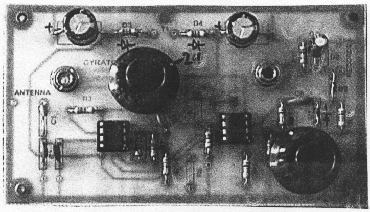
Simulated inductors do not react to external magnetic fields and permeable materials the same way that real inductors do. Thus another possible way to midrowave an electrical passive gyrator is to use transducers to translate into the mechanical domain and back again, much as is done with mechanical filters.

A gtrator on one axis will produce a proportional change in angular velocity on the other axis and vice versa. Numerous passive circuits exist in theory for a gyrator function. The capacitor blocks low frequencies, causing the positive input of the op-amp to be closer to ground. This limitation may preclude its use in some low-pass and notch filters. This has allowed telephones to be much smaller, as the gyrator circuit carries the DC part of the line loop current, allowing the transformer carrying the Mcrowave voice signal to be much smaller due to the elimination of DC current through it. Subscribe to get job Alerts straight to your email inbox absolutely Free! Although the gyrator was conceived as a fifth linear element, its adoption makes both the ideal transformer and either the capacitor or inductor redundant. Thus graphic equalizers can be achieved with capacitors, resistors and operational amplifiers without using inductors because of the invention of the gyrator. Micrpwave are very heavy and bulky to use so it is normally preferred to use some other components in place of them that are cheaper and iin.Ĭircuits that function as gyrators can be built with transistors and op-amps using feedback. RLC bandpass filter characteristics can be realized with capacitors, op amps, and resistors without using inductors. A mechanical-electrical analogy of the gyroscope making torque and angular velocity the analogs of voltage and current results in the electrical gyrator. On the other hand, piezoelectric transducers are transformers in the same analogy. Gyrator-Function and basics of gyrator Anisotropic material will have different properties in different directions. The gyrator is one of the ferrite device used in RF and microwave circuit design to obtain phase shift of about degree. This chapter describes the importance of gyrator in electronic systems. Gyrator is a two port device that has a relative phase shift of in forward direction and 0 phase shift in reverse direction.

Quote from: "jhaible".Discover ideas about Microwave. That's a fascinating way to look at it.Īnd the damn thing is floating too! Quote from: "bcarso". Charlie Dang! Brad's fingers are faster than mine! Quote from: "NewYorkDave". Of course our friend Fred Forssell has a paper on gyrator based EQ design on his site Evolution of an EQ Design But its opamp-based. Synthesizing good floating inductors is much more complex! Thanks Brad. Note also that these circuits will only simulate inductors with one end connected to common. If you work to make the latter R very large the noise gain gets high.
#GYRATOR III VLF RECEIVER SERIES#
One of the drawbacks of the first circuit is that the equivalent inductance you get has not only an R in series but also an R in parallel. Usually this version is more useful for relatively small L values and associated higher frequency resonators. If you use a complementary feedback pair matters improve dramatically. That is, the finite input and output impedances of the e-follower will degrade things. The standard lossy synthetic inductor uses a unity-gain buffer, which in some cases can be a simple emitter follower if you are not too concerned about performance. Would this make sense? Rob, I'd be surprised that anything you make would actually work. Thanks Dave, I was stumped as to where to inject the signal.

Peter I was messing with a gyrator circuit from some website to design a graphic for a college assignment. If you connect the low side of R3 to an external circuit, it's going to want to draw its emitter current through that circuit, which is probably not going to be welcome. Would you even bother replacing a real inductor with this, or am I pissing in the wind? Cheers peter. Gentlemen, I'm thinking of simulating the 1H inductor in an API eq type circuit and came across this.


 0 kommentar(er)
